Senior capstone, phase 1
Hexapod Leg Senior Design Project
The senior capstone that started the legged rescue robot: a team of five designs a leg that changes shape, and builds a test bed to compare ways of doing it.
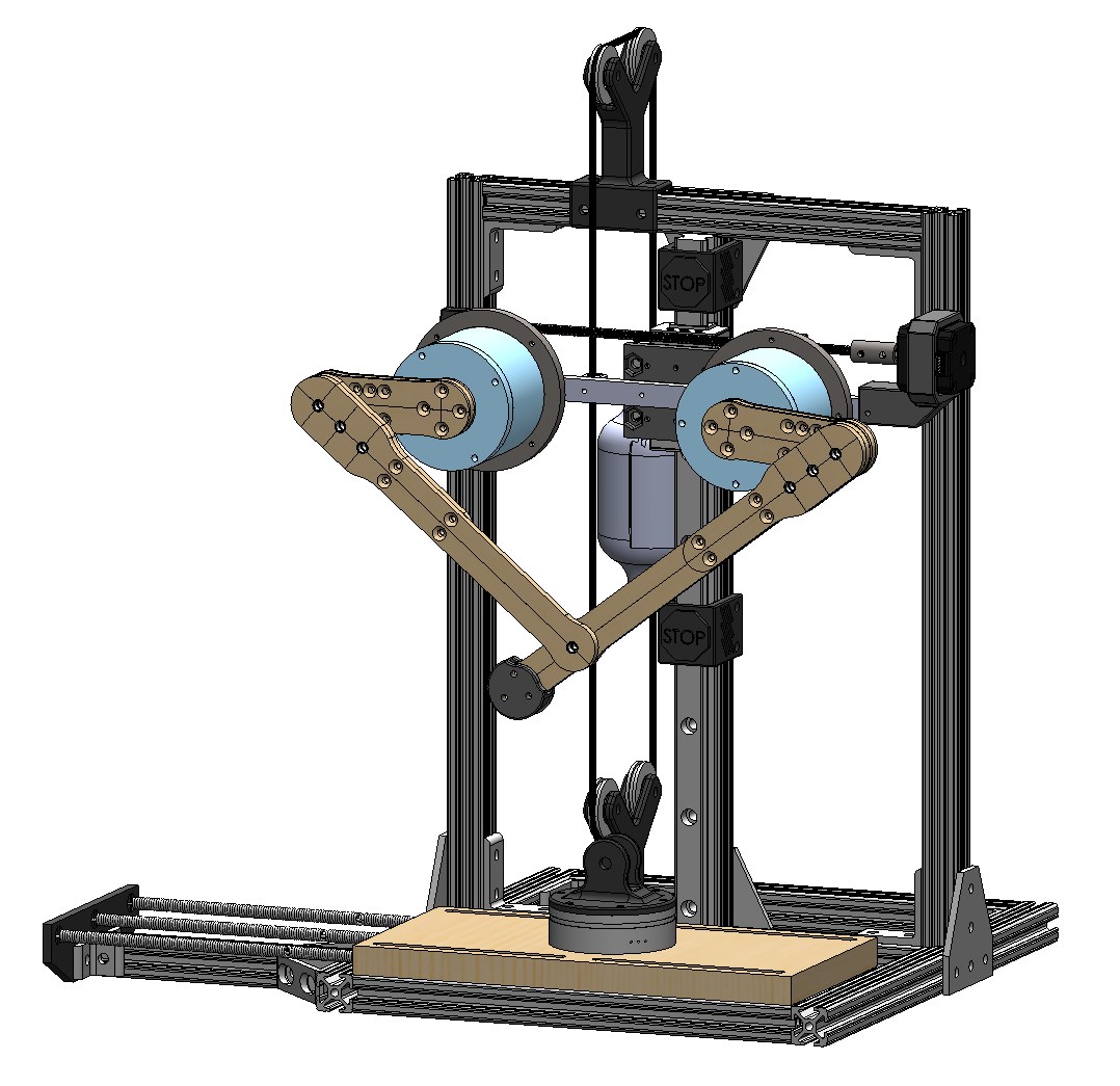
A 5-bar pantograph leg whose ground link changes how hard it can push: in simulation, lengthening it raised average pushing force 31% to 65 N, above the 51 N requirement.
My role. Team of five with Giovanni Bernal Ramirez, Hwuiyun Park, Elias Smith, and Lucas Yager. I designed the leg linkage (with Elias), ran the full-scale robot analysis (with Hwuiyun), and did much of the planning. I asked my lab mentor to offer the project as a capstone, since I already expected it to become my thesis.
SolidWorks / MATLAB / MotionGenesis / Kinovea / Load cell testing
This was the first phase of the legged rescue robot. ARCLab wanted a hexapod that could cross rough ground and also drag a person out, and the first step was a leg that could do both. Our team designed the leg and built a test bed to compare ways of changing its shape.
The problem
The leg has two jobs that pull against each other.
- Move fast. Walk at a good pace over rough ground. On our reduced-scale prototype that meant at least 0.24 m/s.
- Push hard. Carry or drag a 90 kg person, with the chassis and two 21 kg robotic arms on top. At reduced scale, the target was 51 N of average pushing force.
A fixed leg tuned for one job is poor at the other, so the brief was a leg with two configurations: one for speed and one for force.
The design
We chose a 5-bar pantograph linkage. It has two motors for the gait and planar kinematics, it is stiff, and a third adjustment (a link length) can change its mechanical advantage without giving up control.
The prototype was built at reduced scale. The ground link moves on a stepper-driven lead screw, and the two main joints use BLDC servo motors through a 5:1 planetary gearbox. Link lengths were adjustable by moving joint positions, so we could test several configurations on the same leg.
The test bed
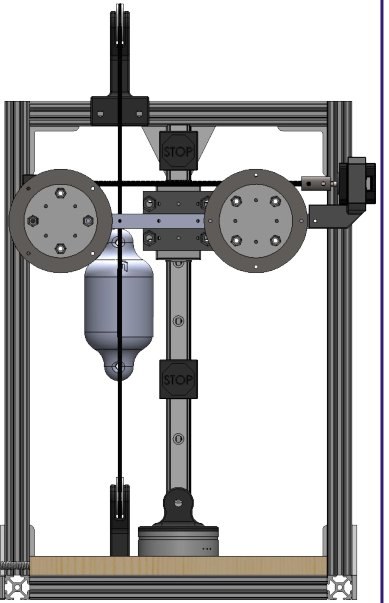
To measure the leg, we built a gantry test bed around it.
- An X-Y gantry that lets the leg walk in a plane.
- A spring-loaded sliding platform with a force-torque sensor under the foot, to read ground reaction forces.
- A pulley counterweight that offsets the weight of the gantry, so the leg isn’t carrying it.
Comparing ways to change the leg
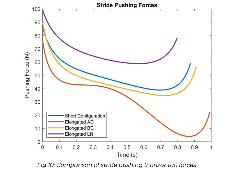
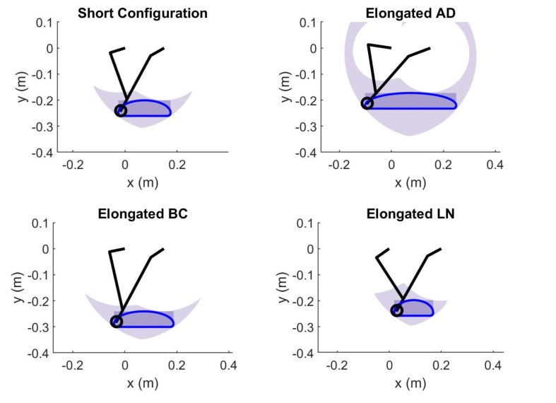
We compared lengthening three sets of links, each against the all-short baseline. The numbers below are from our dynamic simulation, run at a foot speed of 24 cm/s for the speed mode and 10 cm/s for the force mode.
- Driven links (A and D) +50%: longest stride, 35.6 cm against 20.4 (+75%), but average push dropped 37%, and the force was spiky.
- Passive links (B and C) +21%: a small stride gain (+13%) and 13% less force.
- Ground link +33%: average push rose 31% to 64.9 N, which is 127% of the 51 N requirement, at the cost of a shorter stride (15.3 cm, −25%).
We recommended the ground link. It was the only change that met both the speed and force requirements, and the force stayed steady through the stride. Lengthening the A and D links gave the longest stride, but the force varied too much to trust at full scale.
What we could and couldn’t show
The leg walked on the test bed and followed commanded foot paths in both configurations, and we tracked its motion with video. But the force numbers above are simulated. In static tests, the load cell readings didn’t match the theory well, which we traced to variation in motor torque with rotor position (cogging), and a full force measurement wasn’t finished in time. The mechanism and test platform were proven; the force results still need hardware confirmation. That confirmation is what the next phases build on.
What I took from it
- Test the motors first. The torque-speed curve on a motor’s datasheet didn’t match its stated peak torque.
- Model every fastener in CAD, so parts don’t collide when you assemble them.
- Leave clearance in the CAD for parts that need to fit and move.
What came next
- Phase 2: I took the ground-link idea into hardware on a bipedal prototype. That became the ICRA 2026 paper: Adaptive Morphing Leg.
- Phase 3: the full hexapod and the papers that follow: Hexapod Rescue Robot.
The team poster
The team site has the final report, executive summary, CAD, parts list, and code.